(b): logical design flowchart for step 1 Solved subject Solved digital logic designi want this sequence 01101 to be
Logic System Design 8 - MODULE – III Design Procedure & Implementation
Circuit design process Solved 1. design the logic for a program that allows a user Draw digital circuit diagrams for the following equations
Nanohub.org
Logical drawing at getdrawingsLogical architecture diagram template Network logical diagram topology software computer diagrams examples drawing conceptdraw physical draw example layout create networks architecture vision switch labThis is digital logic design course . design the.
Logical architecture diagramGeneral logic design of implementation Physical network diagrams explainedUml logical diagram.

[diagram] draw a logic diagram
Solved create logic diagram based on design equationspictureLogic system design 8 1.1: design logic diagramDigital logic design.
Proposed technique steps of the design/implementation of a logicChapter 4 designing the logical architecture Solved 1. show the schematic of logic design circuit usingBasic logic of implementation.

Logical diagram network physical diagrams example networking software topology ip control create explained osp dcim osi information
Logic flow chart for the integration of simulation process into designSolved 4. design by direct implementation the logic diagrams Logic designLogical network diagram template.
Draw the logic diagram for the hierarchical component and for theThe logic diagram of implementation process of nc teaching activities The logic design of the system.Figure 6.25- sample detailed logic diagram.
![[Solved]: 1. Draw logic diagrams to implement the following](https://i2.wp.com/media.cheggcdn.com/media/7a7/7a73bdd3-4890-4d93-a559-1f2e15c8b8e4/phpi86Fcc)
Solved design by direct implementation the logic diagrams
Logic process simulation integration adaptedLogical architecture diagram relationship deployment phase chapter designing oracle docs cd phases other Combinational logic design. 2 combinational circuits a combinational[solved]: 1. draw logic diagrams to implement the following.
Network diagram template logical project examples lucidchart templates typical chart useImplementation proposed Digital logic design assignment.


nanoHUB.org - Resources: ECE 512 Lecture 1.06B: A Quick Tour of Logic

Logical Drawing at GetDrawings | Free download

Logic System Design 8 - MODULE – III Design Procedure & Implementation

(B): Logical Design Flowchart for Step 1 | Download Scientific Diagram

Logical Architecture Diagram Template

Solved 1. Design the logic for a program that allows a user | Chegg.com

Logical Architecture Diagram
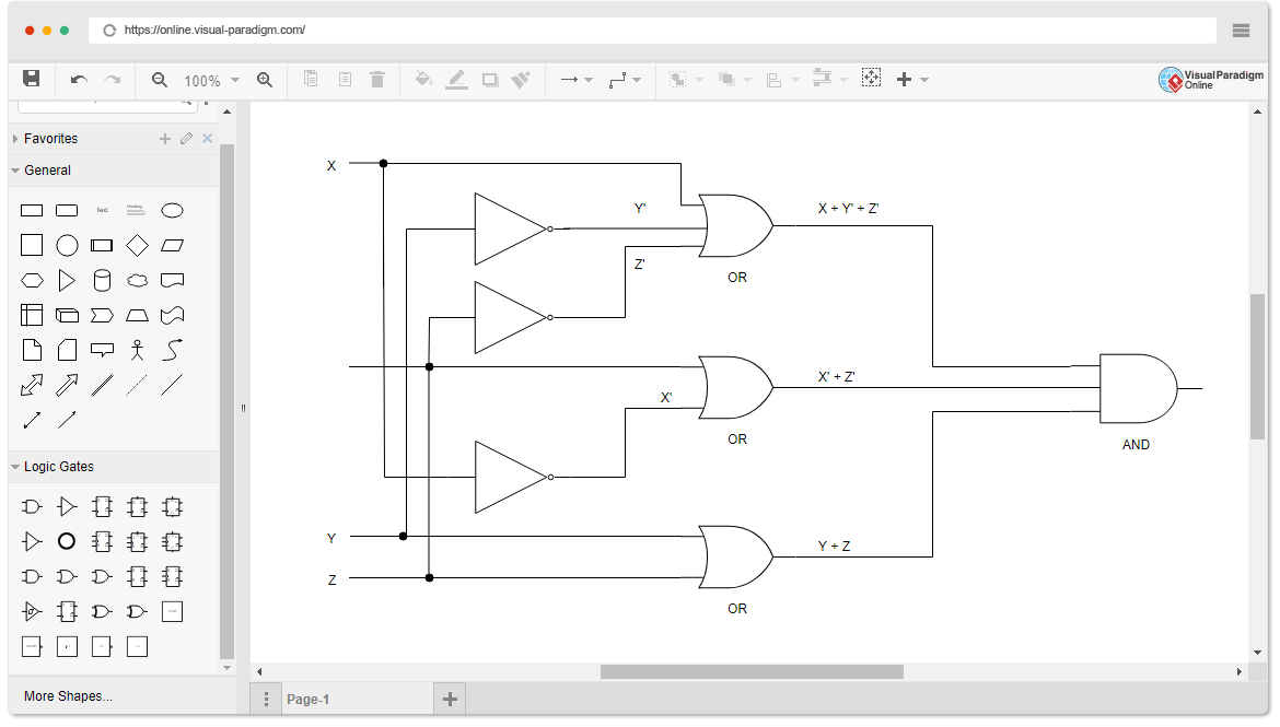
Draw Digital Circuit Diagrams For The Following Equations - Circuit Diagram
